The NRCA Roofing Manual: Membrane Roof Systems—2007 was issued this month and contains several new details addressing construction scenarios that were not included in the fifth edition. (For more information about the manual and its changes, see "The new manual," on page 23.)
One new detail is BUR-24S, "Mop- or Cold-applied Base Flashing at Through-wall Scupper." Scuppers provide an outlet for water from a parapet wall and are a source of drainage. They can discharge water into a conductor head and downspout, discharge directly into a gutter or be extended to allow unrestricted discharge of water.

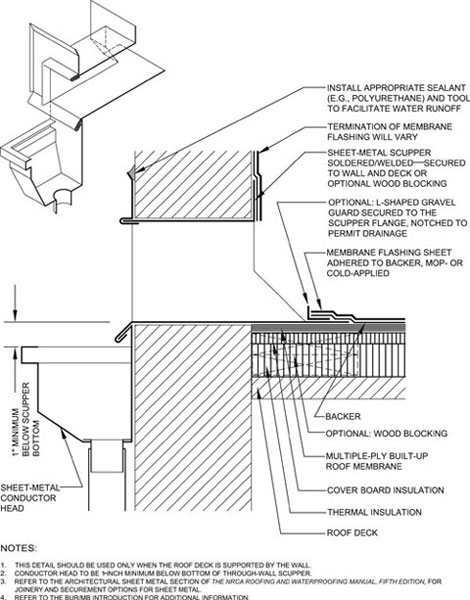
Detail BUR-24S from The NRCA Roofing Manual: Membrane Roof Systems—2007
BUR-24S shows a two-piece scupper constructed with sheet metal. The scupper piece located inside the wall is referred to as a scupper liner, and the other piece is an exterior closure flange installed on the wall's outside face. The top and sides of the closure flange are formed to accept sealant; the bottom flange is locked to the conductor head. The top of the conductor head should be 1 inch below the base of the scupper, and NRCA recommends all scupper joints be soldered or welded. In addition, the scupper assembly should be secured to the wall and deck or optional wood blocking.
On the interior side, an optional L-shaped gravel guard may be installed. The gravel guard should be notched to permit drainage, as well as secured to the scupper flange and flashed with a backer sheet and membrane flashing sheet.
If scuppers are the primary drainage devices, the elevation of a through-wall scupper's base should be flush with the roof surface and not inhibit water flow. There are many seams and component attachments at scupper locations; therefore, it is important to keep the area free from standing or ponding water. Keeping the bottom of a scupper at the level of the membrane or insulation may not allow for positive drainage because the addition of a stripping ply and/or gravel stop tends to prohibit positive drainage. NRCA recommends the use of a drainage sump at the scupper opening.
A cut-away view is included to illustrate the configuration of the scupper liner, exterior closure flange and conductor head.
Joan P. Crowe, AIA, is an NRCA director of technical services.

