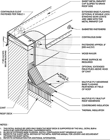
NRCA's Construction Details section of The NRCA Roofing and Waterproofing Manual, Fifth Edition, provides about 450 details for the most common low- and steep-slope roof systems. NRCA's detail BUR-1, "Metal Parapet Cap (Coping) and Base Flashing," which provides built-up roofing (BUR) flashing and metal parapet cap installation information (see figure), first was provided in 1985 as "Built-up Roofing Detail J" in The NRCA Roofing and Waterproofing Manual, Second Edition. Although reformatted and renumbered, this detail has been in each NRCA roofing and waterproofing manual since 1985.
The metal coping cap traditionally is depicted with a joint cover plate. BUR-1 in the manual's fifth edition does not provide specific direction for joining the sheet-metal parapet cap. To accommodate for the multiple acceptable methods of joining sheet-metal caps, as well as other sheet-metal profiles, a Sheet Metal section now is included in the Construction Details section of the manual's fifth edition.
There are six methods shown for installing sheet-metal parapet cap joints. (See SM-16, SM-17 and SM-18 in the Construction Details section of the manual's fifth edition.) Contractors and architects have options for sheet-metal joinery. The cap remains sloped toward the roof side to provide for positive drainage.

A continuous cleat on the front face of the coping cap is necessary for uplift resistance. There is no sealant shown between the drip edge and front face of the parapet wall. This allows moisture that gets under the coping to dissipate and not become trapped, preventing possible deterioration of the substructure.
BUR-1 shows the membrane flashing extending over the top of the parapet under the metal coping cap. This is recommended as secondary protection from water infiltration. In the early details (second edition and third edition), a 12-inch- (300-mm-) wide felt piece was located under the joints only. In the manual's fourth edition, a continuous but separate liner was shown under the sheet-metal cap. In the fifth edition, the membrane flashing is shown extended over the wall under the metal cap with an option to terminate the flashing membrane under the back face of the coping and install a continuous liner.
As BUR flashing materials progressed, the fabric and mastic ("three course") used to complete the installation at the top edge of the flashing membrane became optional in the third edition and fourth edition and were completely omitted in the current detail. Mechanical fasteners are used to secure the membrane flashing at the parapet's top.
COMMENTS
Be the first to comment. Please log in to leave a comment.