The 2016 edition of ASCE 7, "Minimum Design Loads and Associated Criteria for Buildings and Other Structures," became available in June and replaces the 2010 standard. ASCE 7, issued by the American Society of Civil Engineers (ASCE), provides information that allows designers to determine various types of loads and load combinations on buildings. The 2016 edition is referenced in the 2018 editions of the International Building Code and International Residential Code.
Some wind load provisions in the new edition have changed dramatically from those in the 2010 publication. The loads on roof systems greater than 60 feet above grade are somewhat less than or equal to loads derived from the 2010 edition. However, for many roofs that are 60 feet or lower, the loads have changed substantially, and the roof zone layout is quite different. For those familiar with calculating loads in accordance with the 2010 edition, the transition to the 2016 edition will be easy. However, field crews will have a far greater challenge correctly installing attachments at the new roof zones unless designers make an effort to simplify the zone layouts.
The 2016 changes that pertain to the roofing industry include:
- New wind speed maps (including increased mean recurrence interval for Risk Category IV buildings)
- A new ground elevation factor in the velocity pressure equation
- Removal of the truncation of Kz below 30 feet
- Changes in roof pressure coefficients and zones for low-rise buildings
- The addition of pressure coefficients for rooftop photovoltaic (PV) panels
- Loads are now provided for rooftop equipment above 60 feet
- Additional Commentary regarding "open patches" in the surrounding terrain
Following is an overview of these additions and changes. I do not address changes that only pertain to primary structural elements such as beams, columns, shear walls and diaphragms that provide overall support and stability for buildings.
The maps
The basic (design) wind speed for the lower 48 states had been uniform outside the hurricane-prone region since the 1995 edition of ASCE 7. However, this no longer is the case as illustrated in Figure 1, which is an adaption of Figure 26.5-1B.
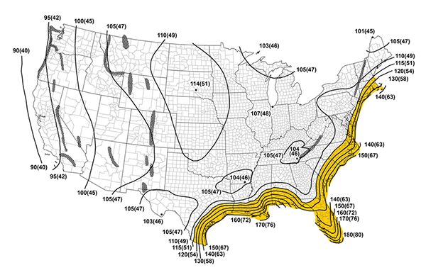
Figure 1: Risk Category II wind speeds in ASCE 7’s 2016 edition. The shaded area indicates a hurricane-prone region. (Map reprinted with permission from ASCE.) |
Basic wind speeds outside hurricane-prone regions are derived from historical weather records. The early 1990s was the last time the historical records were analyzed before the 2016 edition. For the 2016 edition, the National Institute of Standards and Technology released a major analysis of wind speed data collected by the National Weather Service (NWS). In addition to nearly 20 years of additional data, the data set includes more NWS reporting stations (485 stations for the previous analysis versus 575 stations for the new analysis).
Outside the hurricane-prone region, the new wind speeds generally decrease about 5 to 15 mph everywhere except in the northern Great Plains region where they remain about the same as in the 2010 edition. Note on Figure 1, there are point values (for example, 101 and 104) that are provided to aid interpolation. However, rather than interpolate manually, the basic wind speed quickly can be found by entering a building's address in the Applied Technology Council's (ATC's) website, windspeed.atcouncil.org. The website currently provides wind speeds for the 2010 and earlier editions; however, it will be updated to provide the 2016 wind speeds.
The basic wind speed also can be found using the ASCE Hazard tool at www.ascetools.org. The tool also provides information about other hazards.
Risk Category III and IV
In the 2010 edition, Risk Category III and IV had the same mean recurrence interval (MRI) for wind loads, so one map was provided for both categories. In the 2016 edition, Risk Category IV buildings (such as hospitals, police stations and fire stations) now have a higher MRI, which results in a basic wind speed increase of about 5 to 10 mph (depending on building location) compared with Risk Category III buildings (such as schools). With this change, there now are separate maps for Risk Categories III and IV. Risk Category IV buildings will be designed for stronger, rarer wind storms and the related wind design is consistent with snow, ice and earthquake design, which previously required higher loads for this category.
Hurricane-prone regions
The basic wind speeds in hurricane-prone regions are derived from modeling rather than historical records because of their infrequency. For the continental U.S., the Risk Category I, II and III 2016 maps reflect revisions, which show slightly reduced speeds in the northeast extending from Maine to Virginia. The hurricane wind speeds are unchanged from Texas to the Carolinas and for Guam, the U.S. Virgin Islands and American Samoa.
Hawaii
Maps now are included for each of the Hawaiian Islands. These are microzoned "effective" wind speed maps that include the wind speed-up effect of topography. Inclusion of topographic effects will simplify load calculations. However, local site conditions of finer toposcale, such as ocean promontories and local escarpments, still should be examined by the designer.
Special Wind Regions
The boundaries of some Special Wind Regions (which are mountainous areas) have changed. The ATC website indicates when a building is located in a Special Wind Region. The authority having jurisdiction should be consulted for the basic wind speed within Special Wind Regions.
Ground elevation factor Ke
The ground elevation factor, Ke, is a new factor in the velocity pressure equation. Ke is an adjustment for air density. The higher the ground elevation, the less dense the air. With reduced density, a given wind speed exerts less wind pressure. For locations such as central Iowa where the ground elevation is somewhat less than 1,000 feet above sea level, the load reduction is insignificant for low-rise buildings. However, for tall buildings at this ground elevation, the load reduction can reduce the required uplift resistance by one or more levels (for example, FM 1-150 versus FM 1-165 depending on roof height).
Ke has much greater influence for locations at higher elevations, such as Denver (5,280 feet above sea level). A system with an FM rating of 1-90 in the corner zone would be sufficient for a Risk Category II building in exposure B with a 30-foot roof height if the elevation factor reduction is not taken whereas an FM 1-75 rating is sufficient with the reduction.
The standard permits using Ke=1 for all elevations (meaning no reduction as a result of ground elevation).
Truncation of KZ
ASCE's Table 26.10-1 provides a velocity pressure coefficient (KZ), which accounts for the exposure (B, C or D) and the height of the building. In the 2010 edition, for buildings located in exposure B (suburban and urban areas), one coefficient was used for roof heights of 30 feet or less. In the 2016 edition, a components and cladding coefficient (which includes roof systems) is given for roof heights of 30, 25, 20 and 15 feet (0.70, 0.66, 0.62 and 0.57, respectively). For roof heights below 30 feet, removing the truncation reduces the load.
As an example of the magnitude of the load reduction, consider a building in central Iowa. A system with an FM rating of 1-75 in the corner zone would be sufficient for a Risk Category II building in exposure B with a 15-foot roof height if the 2010 truncation coefficient of 0.70 is used. If the 2016 coefficient of 0.57 is used, a 1-60 rating is sufficient.
Roof pressure coefficients
ASCE's Table 30.3-2A provides Component and Cladding external pressure coefficients for buildings 60 feet or less with slopes of 1 1/2-in-12 or less. In previous editions, there were three roof zones: 1 (field), 2 (perimeter) and 3 (corner). With the 2016 edition, a fourth zone has been added, 1', which also is a field zone. However, 1' does not apply to smaller roofs, so this new coefficient will not apply to many buildings. The coefficient for the 1' zone is -0.9, which is slightly less than the field coefficient in the 2010 edition.
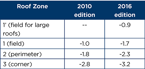
Figure 2: These coefficients are for an effective wind area of 10 square feet or less. |
The magnitude of the coefficients for zones 1-3 has increased, as shown in Figure 2. Note the 2016 zone 1 field coefficient is nearly as large as the 2010 zone 2 perimeter coefficient.
Some examples illustrate various ramifications of the coefficient changes. Consider a Risk Category II building in exposure B with a 30-foot roof height in central Iowa. For the corner, the allowable stress design (ASD) load is 36 pounds per square foot (psf) when using the 2010 edition. It is 37 psf when using the 2016 edition. Although the pressure coefficient increased from -2.8 to -3.2, the load only slightly increased because there was an offset caused by the decreased wind speed and ground elevation factor. For this building, a system with an FM rating of 1-75 in the corner zone is sufficient for both editions.
Now consider the roof's field. The ASD is 14 psf when using the 2010 edition and 20 psf when using the 2016 edition. In this case, because of the larger percentage of the coefficient increase, the load increase is not totally offset by the decreased wind speed and ground elevation factor. However, a system with an FM rating of 1-60 in the field is sufficient for both editions. For this building, the 2016 changes do not result in a change in system ratings.
But what about a Risk Category II building in exposure B with a 30-foot roof height in central Florida? For the corner, the ASD load is 89 psf when using the 2010 edition. It is 101 psf when using the 2016 edition. Unlike the Iowa case, the pressure coefficient increase of -2.8 to -3.2 was not offset by a decrease in the wind speed or the ground elevation factor. So for this building, a system with an FM rating of 1-180 in the corner zone is sufficient for the 2010 edition, but a 1-210 rating applies when the 2016 edition is used.
Now consider the roof field of the Florida building. The ASD is 35 psf when using the 2010 edition and 56 psf when using the 2016 edition. A system with an FM rating of 1-75 in the field zone is sufficient for the 2010 edition, but a 1-120 rating applies for the 2016 edition. As a result, the 2016 changes result in a significant increase in system ratings.
In general, for one- and two-story buildings outside hurricane-prone regions in the lower 48 states, there will not be an increase in system ratings because of the reductions provided by ground elevation and/or wind speed and conservatism of the lowest FM rating. However, for taller buildings 60 feet high or less, as well as buildings in coastal Alaska and many buildings within hurricane-prone regions, there will be an increase in system ratings, and the increases will be significant in many cases.
For low-slope roofs above 60 feet, there is no change in pressure coefficients or roof zones.
Roof zone layouts
In previous editions, roof zone dimensions were a function of the least horizontal dimension of the roof and roof height. In the 2016 edition, the zone dimensions only are based on roof height. ASCE's Table 30.3-2A shows zone layout. However, what is shown only applies to roofs of a certain size and height. The standard's Commentary shows three additional layouts and describes a fourth condition for a total of five zone layouts:
- Buildings with the least horizontal dimension greater than 2.4 times the roof height. Consider a roof that is 600 x 1,000 x 30 feet high as shown in Figure 3. This building has four zones. Note the corner zone is L-shaped. Zones 1 and 2 are each 18 feet wide. With the 2010 edition, this building would have three zones and the perimeter would be 24 feet wide. Although the 2016 zone 2 is not as wide as the 2010 zone 2, the 2016 zone 1 load is nearly as large as the 2010 zone 2 load.
- Buildings with the least horizontal dimension greater than 1.2 times the roof height but less than 2.4 times the roof height. Figure 4 shows a roof that is 50 x 100 x 30 feet high with three zones for the 2010 and 2016 editions. The perimeter is 5 feet wide with the 2010 edition and 18 feet wide with the 2016 edition. Installing fasteners or foam ribbon adhesives could be simplified by treating the zone 2 shaded areas as zone 3. Simplifications such as this have little cost effects, and they increase the potential for crews to install attachments at the intended spacings.
- Buildings with the least horizontal dimension less than 1.2 times the roof height and the largest horizontal dimension greater than 1.2 times the roof height. Consider a roof that is 30 x 50 x 30 feet high (see Figure 5) and has two zones for the 2016 edition and three zones for 2010. The perimeter is 3 feet wide with the 2010 edition. The shaded areas indicate simplification by treating the area as zone 3 rather than zone 2.
- Buildings with the largest horizontal dimension less than 1.2 times the roof height. Figure 6 shows a roof that is 20 x 20 x 20 feet high that has two zones for the 2016 edition and three zones for 2010. The perimeter is 3 feet wide with the 2010 edition.
- Buildings with the largest horizontal dimension less than 0.4 times the roof height. A roof that is 19 x 19 x 50 feet high has an entire roof area in zone 3 for the 2016 edition.
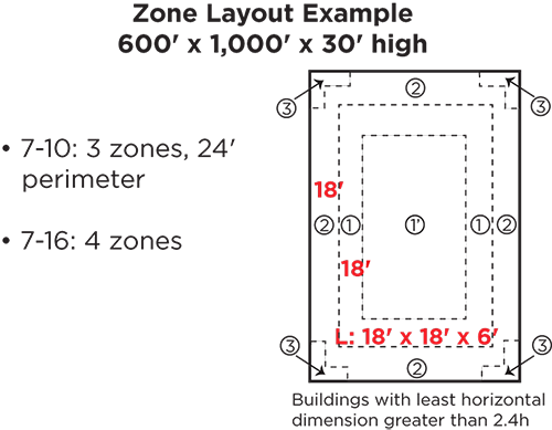
Figure 3: Zone layout example (600 x 1,000 x 30 feet high) |
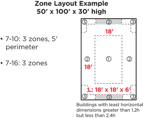
Figure 4: Zone layout example (50 x 100 x 30 feet high) |
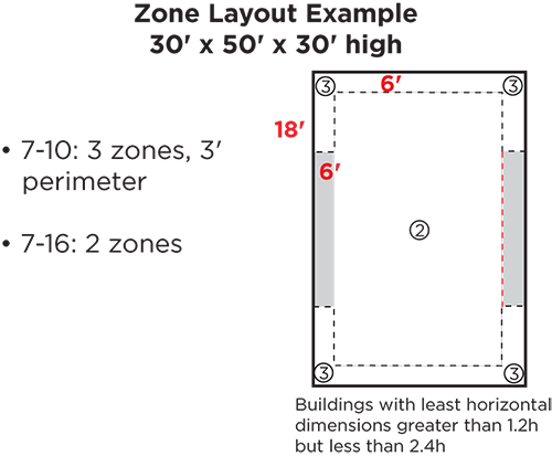
Figure 5: Zone layout example (30 x 50 x 30 feet high) |
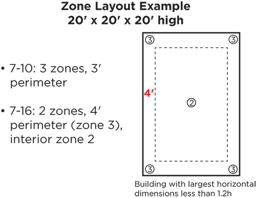
Figure 6: Zone layout example (20 x 20 x 20 feet high) |
The coefficient and roof zone layout changes in the 2016 edition are based on additional wind tunnel studies and compared with full-scale field data. Jon Peterka, a world-leading wind engineer from Fort Collins, Colo., was commissioned by five industry groups to review the changes and found the wind tunnel studies the 2016 changes are based upon are valid.
Although valid, the new zone layouts no longer are intuitive. I recommend designers show the roof zones on their roof plans and consider simplifying the zone layouts so roofing crews are afforded greater opportunity for correctly spacing attachments.
Roof pressure coefficients
The 2010 edition provided coefficients for hip and gable roofs with slopes greater than 7° to 27° (1.5-in-12 to 6-in-12), and greater than 27° to 45° (6-in-12 to 12-in-12). The 2016 edition provides coefficients for slopes greater than 7° to 20° (1.5-in-12 to 4.5-in-12), greater than 20° to 27° (4.5-in-12 to 6-in-12) and greater than 27° to 45° (6-in-12 to 12-in-12). In some cases, the magnitude of the coefficients have increased.
Rooftop PV
2016 is the first edition to provide wind load criteria specific to rooftop solar panels. Before the 2016 edition, SEAOC Report PV2-2012, "Wind Design for Low-Profile Solar Photovoltaic Arrays on Flat Roofs," could be used to determine wind loads. However, now that loads are addressed in ASCE 7, it should be used to calculate the loads instead.
Rooftop equipment
Previous editions did not provide load criteria for equipment on roofs greater than 60 feet above grade. The 60-foot limit has been eliminated in the 2016 edition. The criteria in sections 29.4.1 and 30.10 now apply to all roof heights.
The 2016 edition also provides new information regarding loads on equipment screens in Section C29.4.1.
Open patches
Open patches, such as highways, parking lots and playing fields, cause local increases in wind speeds at their edges. The 2010 edition provided commentary regarding exposure B with open patches. Additional guidance is provided in the 2016 edition. Some exposures that might be assessed as being exposure C could be determined to have a surface roughness that is partway between B and C, which would result in a significant load reduction. The additional commentary guidance facilitates assessing the influence of open patches.
Get the standard
For the first time, an online version of the publication is available at www.asce.org/asce-7. The online version shows redline changes between the 2010 and 2016 editions, and it allows side-by-side display of the standard's provisions and the explanatory information in the Commentary. The online version also will be updated when supplements or errata are issued.
Thomas L. Smith, AIA, RRC, F.SEI, is president of TLSmith Consulting Inc., Rockton, Ill., and a member of the ASCE 7 Task Committee on Wind Loads.
Pro tip
After calculating the ultimate design uplift loads for the various zones, loads are converted to allowable stress design (ASD) loads via the 0.6 W load combination provided in ASCE 7's Chapter 2. The ASD load typically is increased by a safety factor of 2 to determine the minimum passing load achieved during laboratory testing. System resistance commonly is specified by referencing an FM rating. FM Property Loss Prevention Data Sheet 1-29, section 2.2.10.1.1 provides options to secure the roof system at the perimeter and corners.
One option is to use prescriptive enhancements based on the field attachment. However, until the prescriptive enhancements in FM 1-29 are updated to align with ASCE 7-16, I recommend designers specify a system rating for each roof zone to avoid underspecifying the system.
