There have been many instances of aircraft hangars' roof systems being damaged during high winds, yet other buildings' roof systems at an airport and in nearby communities were not damaged. Obviously, the wind did not target the hangars' roof systems, so why did damage occur? The answer lies with the unique characteristics of aircraft hangars, which many roof system designers do not recognize. Following is some information about these unique characteristics and how they contribute to wind-related roof system damage, as well as design solutions that can be implemented to avoid or minimize damage.
Unique characteristics
A distinguishing characteristic of hangars is location. Because an airport's surrounding terrain typically is flat, vegetation is low and there are few nearby buildings, virtually all hangars are in Exposure C as defined in ASCE 7, "Minimum Design Loads for Buildings and Other Structures."
ASCE 7 defines three common exposure classifications: B (urban, suburban and wooded areas); C (open terrain with scattered obstructions and shorelines in hurricane-prone areas); and D (shorelines exposed to wind flowing over open water for a distance of at least 1 mile [1.6 km]). A building's exposure classification strongly influences its wind load. For example, for an enclosed building (a building whose exterior envelope is relatively air-impermeable), the uplift loads on roof systems in Exposure C are 40 percent greater than those in Exposure B, and the loads in Exposure D are 66 percent greater than those in Exposure B. Because of a terrain's influence on wind loads, a windstorm delivers about 40 percent higher uplift loads to roof systems on most airport buildings versus loads delivered to buildings in nearby urban or suburban areas.
According to ASCE 7 Commentary, an estimated 60 percent to 80 percent of all buildings have terrain exposures corresponding to Exposure B. Therefore, hangars are in the rather small population of buildings that receive substantially higher loads than most other buildings in the surrounding vicinity.

Photo courtesy of TLSmith Consulting Inc., Rockton, Ill.
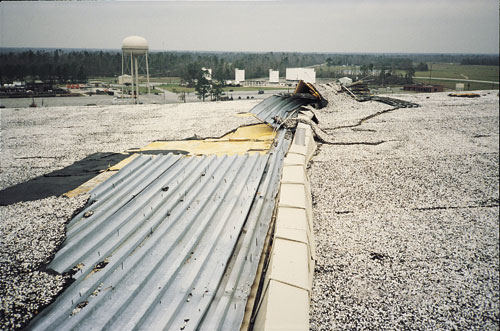
Photo 1: A substantial amount of roof deck material blew off these hangars. At one hangar, many trusses also were blown away. Two nearby fighter aircraft appeared to be damaged, as well.
In addition to the uplift (suction) pressure created as wind flows over a roof, wind can increase or decrease a building's interior pressure. As a result, the total load on a roof assembly is a combination of its internal pressure and external suction. Most buildings have exterior envelopes that are relatively air-impermeable. For these enclosed buildings, internal pressure contributes little to a roof assembly's load. However, if a building envelope is air-permeable (which often is the case with aircraft hangars), the internal pressure is about three times greater than if the envelope were air-impermeable.
The much greater internal air pressure associated with partially enclosed buildings (those with air-permeable envelopes) significantly increases a roof assembly's uplift load. For example, roof system loads on a partially enclosed building are about 27 percent greater in a roof's field, 21 percent greater at the perimeter and 11 percent greater at roof corners than the loads on corresponding roof areas on an enclosed building. Therefore, two buildings that are identical except for envelope permeability will experience substantially different wind loads on their roof assemblies when exposed to the same windstorm.
Although ASCE 7 allows most aircraft hangars to be classified as enclosed buildings, ASCE 7 Commentary states designers should consider classifying hangars as partially enclosed buildings because of the great amount of air leakage that often occurs around large hangar doors. Unfortunately, many designers are unaware of the guidance given by ASCE 7 Commentary, and many hangars are designed as enclosed buildings, which is a nonconservative design approach.
Another reason for designing hangars as partially enclosed buildings is that a fast-moving storm (such as a thunderstorm) may strike a hangar before its large doors are closed. If a hangar's doors are open during a high-wind event, the risk of roof assembly damage is reduced if the building had been designed as a partially enclosed building.
Roof height also affects a roof assembly's uplift load. Except in large urban centers' downtowns, most buildings are less than 30 feet (9 m) high. However, hangars commonly are 40 feet to 50 feet (12 m to 15 m) high. At roof corner areas, the uplift load is about 20 percent greater on a 50-foot- (15-m-) tall building compared with a 20-foot- (6-m-) tall building. Two buildings that are identical except for roof height can have substantially different wind loads on their roof assemblies when exposed to the same windstorm.
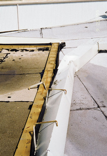
Hangars frequently have gutters, and typically because of large roof areas, the gutters are quite wide—about 12 inches (305 mm). Designers usually adequately consider supporting gutters for gravity loads but seldom design gutters for uplift. Therefore, during high winds, the uplift load on gutters typically is transferred through gutter support brackets. The brackets typically are attached to nailers at a roof's edge or, sometimes, a roof deck. However, because a nailer or deck usually is not designed to account for an uplift load induced by gutters, nailer or deck failure easily can occur (see Photos 2 and 3).

Photo courtesy of TLSmith Consulting Inc., Rockton, Ill.
Photo 2: This hangar had an aggregate-surfaced built-up membrane over two insulation layers; the first layer was mechanically attached to the deck. The 12-inch- (305-mm-) wide gutter was supported on heavy steel brackets, which rested on and extended out about 4 feet (1 m) onto the deck. The straps were screwed to the deck, but the deck did not have enhanced welding to the support structure to account for the uplift load the gutter transferred to the deck. As a result, large areas of the deck blew off in one corner and along the wall on the opposite side.

Photo courtesy of TLSmith Consulting Inc., Rockton, Ill.
Photo 3: This hangar had a modified bitumen membrane adhered over two insulation layers; the first insulation layer was mechanically attached to the metal deck. The wide gutter was not designed for wind uplift. All the gutter's wind load was transferred to the edge nailer, but the nailer attachment did not account for the additional load. The nailer lifted and caused the roof membrane to peel.
The uplift load on a 12-inch- (305-mm-) wide gutter is not trivial. For example, along the perimeter of a 50-foot- (15-m-) tall building located in a 90-mph (40-m/s) peak gust basic wind speed area (which encompasses most of the U.S. mainland) in Exposure C, the design uplift load is 33 pounds per lineal foot (plf) (481 N-m). At the corners, the gutter load is 54 plf (788 N-m). Where the basic wind speed is 130 mph (58 m/s), which is common along much of the Atlantic Ocean's coast and Gulf of Mexico's coast, the gutter load is 112 plf (1634 N-m) at the corners and 68 plf (992 N-m) between the corners. The uplift loads on wide gutters, even in areas with low basic wind speeds, are sufficient to cause roof system damage if they are not adequately accounted for by the designer.
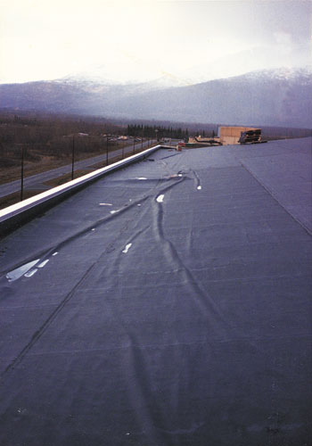
Hangar walls typically are constructed with metal wall panels. Wall panel characteristics can influence loading on metal edge flashings or copings, and the wall panels can influence wind resistances of edge flashings or copings. Because wall panels on hangars typically are profiled (corrugated) rather than flat, it is easy for air to flow underneath edge flashings or copings and contribute to lifting and peeling forces. If edge flashings or copings are attached inadequately, they and the roof membrane typically lift and progressively peel (see Photos 4 and 5).


Photos courtesy of TLSmith Consulting Inc., Rockton, Ill.
Photos 4 and 5: A fully adhered EPDM membrane was installed over mechanically attached polyisocyanurate insulation over a vapor retarder on a metal deck. The hangar's sides had a parapet, and the ends had metal edge flashings. Air was able to enter under the edge flashings at the profiled metal wall panels and cause the membrane and insulation facer to separate from the foam insulation. A substantial amount of membrane detached from the insulation, and one of the field seams ruptured (a secondary failure that occurred after the membrane detached).
The outer faces of edge flashings or copings typically are attached to a metal wall panel with screw-attached continuous cleats. Often, wall panels are so thin screws' pull-out resistances are much lower than would be expected when attached to a thicker metal, such as that associated with most metal roof decks.
Cumulative load increases
The load increases associated with exposure (terrain), internal pressure and roof height are cumulative. For example, compared with a 20-foot- (6-m-) tall enclosed building in Exposure B, roof system uplift loads on a 50-foot- (15-m-) tall partially enclosed building in Exposure C are about 77 percent greater in the corners, 83 percent greater at the perimeter and 106 percent greater in a roof's field.
Design recommendations
Note: The following design recommendations are not necessarily those of NRCA.
The key to avoiding roof assembly blow-offs on hangars is to recognize unique aspects of these buildings and design accordingly. Following are recommendations that should be considered when designing roof systems on hangars in addition to usual design considerations, such as thermal movement and corrosion.
When designing a hangar, a designer should calculate loads on the roof deck and roof covering. The loads may be different because of different "effective wind areas" as defined in ASCE 7, such as the number of square feet of roof area carried by the deck versus the membrane fastener. In most instances, categorizing a hangar as a partially enclosed building is recommended.
If a hangar houses emergency aircraft (such as police or medical evacuation helicopters) or aircraft that have critical national defense functions, the hangar should be classified as an essential facility per ASCE 7. By classifying a hangar as an essential facility, the uplift loads on the roof assembly increase 15 percent. This load increase is intended to give essential facilities additional strength to resist storms stronger than those for which designers typically design.
Although ASCE 7 prescribes certain hangar types to be designed as essential facilities, in many cases it is prudent for a designer to voluntarily design hangars as essential facilities. Although designing conservatively to minimize losses may be an option for many roof systems, the difference is that debris could cause millions of dollars of damage to aircraft. For most buildings, debris would cause much less damage.
For example, if a hangar houses commercial aviation jets, designing it to resist stronger storms is prudent. But if a hangar houses single-engine general aviation aircraft, designing the hangar for typical wind events would be sufficient. When considering whether to voluntarily design for higher loads associated with essential facilities, designers should envision the ramifications of wind-borne roof debris striking aircraft or helicopters within or near the hangar and potential cost of aircraft damage. If the cost of aircraft repair would be much more than the cost of roof system replacement, designating a hangar as an essential facility and spending a little more money to attach the roof system more securely is a wise decision.
Although other items inside a hangar can be damaged by debris, debris hitting aircraft within a hangar or outside on the tarmac is the primary issue. Water damage to hangars' interiors usually is relatively minor.
If a hangar's gutters are wide, designers should calculate the uplift load on the gutters using the overhang coefficient from ASCE 7. There are two approaches for resisting gutter uplift. Gravity-support brackets can be designed to resist uplift loads. In these cases, a bracket should be attached at its low end to a wall and near the bracket's top, similar to the detail shown in Figure 13 in FM Global's "Loss Prevention Data Sheet 1-49" published in May 1998. The gutter also needs to be designed so it is attached securely to the bracket in a way that effectively will transfer the gutter uplift load to the bracket. Bracket spacing will depend on the gravity and uplift load, bracket's strength, and strength of connections between the gutter/bracket and bracket/wall.
The other option is to use gravity-support brackets only to resist gravity loads and use separate sheet-metal straps at 45-degree angles to the wall to resist uplift loads. Strap spacing will depend on the gutter uplift load and strength of the connections between the gutter/strap and strap/wall.
When designing a bracket's lower connection to a wall or strap's connection to a wall, designers should determine the wall panel's thickness so appropriate screw pull-out values are used.
With the first option, the bracket's upper connection typically will be into a wood nailer and that fastener will be designed to carry the gravity load. The bracket's lower connection will resist the rotational force induced by gutter uplift. The lower connection typically will be in a metal wall panel in which case the screw's pull-out value may be quite low. However, because brackets usually are spaced close together to carry the gravity load, developing adequate connection strength generally is not difficult.
Gravity-support brackets usually are made of 1/4-inch- (6-mm-) thick steel and are 1 inch (25 mm) wide. Therefore, if two lower fasteners are needed to resist the load, they are aligned vertically. Note that FM 1-49 recommends placing straps 10 feet (3 m) apart. However, at that spacing with wide gutters, gravity loads and fastener loads induced by uplift are quite high. Although a bracket may be able to carry loads when spaced at 10 feet (3 m), it can be difficult to achieve sufficiently strong uplift connections at that spacing.
With the second option, a minimum of two screws at each end of a strap is recommended. At a wall, screws should be placed side by side rather than vertically aligned so the strap load is carried equally by the two fasteners. When fasteners are vertically aligned, most of a load is carried by the top fastener.
Regardless of the option chosen, the uplift load in the corners is much higher than the load between the corners, so enhanced attachment is needed in corner areas. ASCE 7 provides guidance about determining a corner area's length.
Other considerations
When installing metal edge flashings and copings, follow the guidelines set forth in ANSI/SPRI ES-1-1998, "Wind Design Guide for Edge Systems Used with Low Slope Roofing Systems."
In addition, if cleat, clip or face fasteners are to be placed into metal wall panels, determine the wall panels' thicknesses so appropriate screw pull-out values are used. If a wall panel is profiled, verify the specified fastener spacing is compatible with the panel ribs so the fasteners actually engage the wall panel.
Depending on the basic wind speed and roof system type, edge flashing should be designed to prevent air from flowing underneath it. This prevents the air from contributing to the uplift pressure on the horizontal flange and, in the case of fully adhered membranes, causing a membrane to lift and peel from the insulation.
For a hangar located in an area where moderate winds often are a daily occurrence, I recommend incorporating an air retarder into the roof system. For further information about air retarders, see "Role of air retarders deserves closer scrutiny," October 1991 issue, page 74.
Wind loads on the parapet base flashing can exceed those on the roof itself, as mentioned in ASCE 7's 2002 edition, which will be available later this year (ASCE 7's 1998 edition does not provide guidance for determining parapet loads.) Parapet base flashing experiences the same suction loads as the adjacent roof area. In addition, it can experience positive pressure from the windward side of the parapet if the windward side of the parapet is not sealed, which is the case with most hangar parapets. Therefore, base flashing loads should be calculated so a designer can specify a base flashing that has sufficient blow-off resistance. This particularly is important if a base flashing is mechanically attached rather than fully adhered.
Except for hangars that have structural metal panel roof systems, most hangars have steel roof decks. I recommend screw attaching steel decks (rather than welding) because I believe screws provide greater reliability. Welds can be adequate when properly executed, but poor welds are common.
When reroofing hangars that were designed according to the 1979 or earlier editions of the Uniform Building Code or Standard Building Code or the 1984 or earlier editions of the Building Officials and Code Administrators International's Basic/National Building Code, I recommend designers specify installing additional fasteners to attach a deck to the support structure in the corners and perimeters. These model code editions used the field uplift load in the perimeter and corners, and without enhanced attachment, decks designed according to older editions are vulnerable to blow-off.
Wrapping up
Although aircraft hangars present challenges, when the uniqueness of this building type is understood and attention is given to address the special design aspects of hangars, design solutions and details can be developed that result in reliable roof assembly performance during high-wind events.
Thomas L. Smith is president of TLSmith Consulting Inc., Rockton, Ill.
