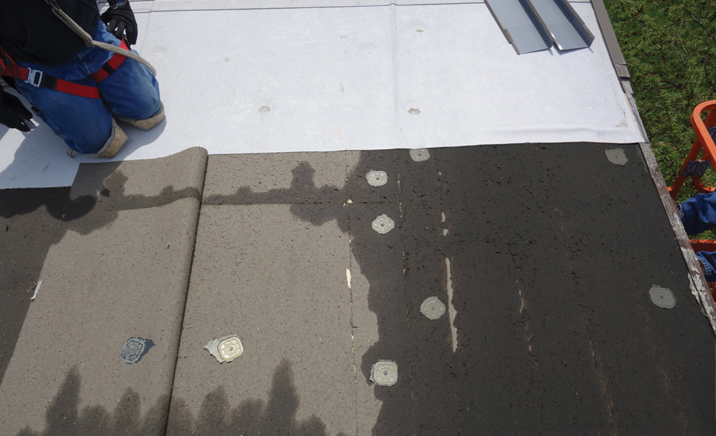
It has long been widely recognized roof membrane blow-off often is caused by inadequate attachment of edge flashings and copings (see Photo 1). A few decades ago, it was common for edge flashings to be attached with cleat clips or to be uncleated. The NRCA Roofing and Waterproofing Manual's 1989 edition and the Sheet Metal & Air Conditioning Contractors' National Association's Architectural Sheet Metal Manual's 1987 edition permitted 4- and 5-inch uncleated vertical faces of edge flashings.
Eventually, it was recognized edge flashings are susceptible to blow-off when they are attached with cleat clips or are uncleated. However, Hurricane Hugo investigations of which I was a part revealed many failures of edge flashings and copings that had continuous cleats. Several of my Hugo recommendations were incorporated into ANSI/SPRI ES-1, "Wind Design Standard for Edge Systems Used with Low Slope Roofing Systems."
Until about a decade ago, it was common for edge flashings and copings to be weaker than the nailers to which they were attached. But with the incorporation of ANSI/SPRI ES-1 into the 2003 edition of the International Building Code (IBC), this has changed. Since the publication of ANSI/SPRI ES-1 in 2003, wind damage investigations have revealed instances where nailers were the weak link in the uplift load path. This is not a new finding (see Photo 2). However, because ANSI/SPRI ES-1 increased attention to edge flashing and coping attachment, nailer failure will become the predominate edge failure mode unless attention also is given to nailer attachment.
ANSI/SPRI ES-1 changes
In 2011, ANSI/SPRI ES-1's title changed to ANSI/SPRI/FM 4435/ ES-1. The 2011 edition is referenced in IBC's 2015 edition (the 2012 IBC references the 2003 edition of ES-1). Nailers were addressed in ANSI/SPRI ES-1's 2003 edition; however, additional information was added to the 2011 edition.
For example, nailer securement load tables were added. Table footnotes include the following notations:
- The tables can be used in lieu of calculations or nailer testing.
- The fastener loads in the table are "working" loads (allowable stress design). Fastener pull-out values from manufacturers often are ultimate values that need to be reduced by a safety factor. Table 2 in the 2003 edition specified safety factors for fasteners in wood, masonry and steel substrates; however, the 2011 edition simply says to use an "appropriate" factor.
- The tables do not give nailer fastener loads in corner zones. Corner loads are derived by factoring the perimeter load as noted in a footnote.
- The "engineer of record" is tasked with designing the nailer for bending, shear and fastener pull-through.
Commentary Section C4.4 notes the nailer securement load tables do not address horizontal loads. If a roof membrane is fully adhered, it is my opinion nailer fasteners typically will have adequate shear resistance. However, if a membrane is mechanically attached and the nailer receives membrane fasteners, the nailer should be designed for the additional load imparted by the membrane (both versions of ANSI/SPRI ES-1 provide guidance for doing so).
In addition, the 2003 and 2011 editions state deteriorated nailers should be replaced. Both editions also state contractors should check existing nailers to ensure they are "well-secured to the building." However, in my opinion, if a designer (architect, engineer or roof consultant) is involved with a reroofing project, the designer should determine whether existing nailers are adequately attached. The 2011 edition gives more stringent criteria than the 2003 edition by requiring fasteners to resist the design wind load rather than the nailers simply being "well-secured."
The Commentary implies the entire load path from the nailers to the foundation should be adequate. For new construction, this is logical. However, for reroofing projects, this can be burdensome. Determining whether an entire load path is adequate can be costly. Additionally, if a load path is inadequate, strengthening it can be expensive. Guidance in the Commentary typically is nonmandatory. Although only the test method portions of ANSI/SPRI ES-1 are referenced by the 2006 and later editions of IBC, the wording in section 3.9.1 of the standard might be incorrectly interpreted by some authorities that have jurisdiction as requiring the Commentary to be mandatory.
With respect to load path, as part of a reroofing project, it is my opinion existing nailers should be attached to their substrate to meet current wind-uplift loads. Depending on a variety of factors (which I would discuss with the building owner), it may not be appropriate to spend the money for other load path improvements.
Common provisions
Both editions of ANSI/SPRI ES-1 have the following nailer provisions of which designers and contractors should be aware:
- Nailers are required to have a minimum 1 1/2-inch thickness.
- The Commentary states nailers should be preservative-treated. As previously discussed, some authorities that have jurisdiction may incorrectly interpret the 2011 edition as requiring preservative treatment. Incidentally, NRCA's 2005 Special Report "Use of treated wood in roof assemblies" advises NRCA believes nontreated construction-grade wood is suitable for nailers provided reasonable measures are taken to ensure the nontreated wood remains reasonably dry during service.
- The Commentary states: "An edge flashing may also function as an air seal, when combined with an air retarder
throughout the field of the roof, by preventing air infiltration under the roofing membrane. To resist air
infiltration, nailers should be sealed to the building with appropriate sealant material. Where multiple courses of
nailers are used, these nailer courses should also be sealed to each other. Butt joints should also be sealed." As
previously discussed, some authorities that have jurisdiction may incorrectly interpret the 2011 edition as requiring
sealed nailers.
In my opinion, if a membrane is mechanically attached, it often is prudent to specify a separate air barrier and sealed nailers. (I prefer butyl sealant for sealing nailers.) It also is important to specify a separate air barrier and sealed nailers if a loose-laid membrane is covered with interlocking insulation panels that have a cementitious coating. However, if a membrane is fully adhered and the system incorporates a vapor retarder or air barrier, field performance has shown nailers do not need to be sealed.
My recommendations
In addition to the requirements and nonmandatory guidance given in ANSI/SPRI ES-1, I recommend the following:
- The designer of record should determine nailer loads and specify nailer attachment. If a reroofing project has no designer involved, the roofing contractor should determine nailer loads and attachment or retain a designer to perform these tasks.
- If there is a gutter and the gutter brackets are attached to the nailer, the design uplift load on the gutter should be determined and the amount of the gutter load that is transferred to the nailer should be considered when designing the nailer attachment. When gutter brackets are attached to nailers, the additional uplift load can be significant, particularly for wide gutters. For gutter wind design and testing criteria, see ANSI/SPRI GD-1, "Structural Design Standard for Gutter Systems Used with Low-Slope Roofs."
- Some building designs employ a bearing wall that supports the inner edge of the nailer, a brick veneer that supports the other edge with rigid insulation, and an airspace between the bearing wall and brick veneer. This situation presents a design challenge. Although the brick provides support for nailer gravity loads, it provides little opportunity for achieving uplift resistance at the nailer's outer edge. In terms of uplift, the nailer is cantilevered from the bearing wall. There are different ways to provide adequate nailer uplift resistance; the key is to make the effort to design a suitable attachment to avoid a nailer failure as shown in Photo 3.
- For reroofing projects, before membrane tear-off, remove a few pieces of edge flashing or coping (including sections located in the corner zones and outside of them) to determine their attachment. Have a designer evaluate the attachment and determine whether additional attachment is needed to resist the current design wind load.
- When nailers are attached with bolts, a least 3/4 of an inch of wood should be left below the washer to avoid the nailer pulling over the washer during high winds.
It is vital nailers be appropriately designed and installed to achieve good wind performance.
Thomas L. Smith, AIA, RRC, F.SEI, is president of TLSmith Consulting Inc., Rockton, Ill.
Know your standards
ANSI/SPRI ES-1 addresses two primary elements of edge system wind design: determining wind loads and determining wind resistance via laboratory testing. For determining wind loads, the 2003 edition is based on the 2002 edition of ASCE 7, "Minimum Design Loads for Buildings and Other Structures." The ANSI/SPRI ES-1's 2011 edition is based on ASCE 7's 2005 edition. With respect to wind loads on roof systems, the 2002 and 2003 editions of ASCE 7 are the same. However, the 2012 and 2015 editions of the International Building Code (IBC) reference ASCE 7's 2010 edition, which is quite different from the previous edition. (For more information about the changes, see "Mapping the 2010 wind changes," August 2010 issue.) IBC references ASCE 7 for determination of wind loads. Therefore, when working with the 2012 or 2015 editions of IBC, make appropriate adjustments when using ANSI/SPRI ES-1.
ANSI/SPRI ES-1 includes test methods for evaluating wind resistance of edge flashings and copings. However, these tests do not typically evaluate nailer resistance. Nailer resistance is evaluated by calculations or by using nailer tables in the 2011 edition of ANSI/SPRI ES-1. The test methods are the only portion of ANSI/SPRI ES-1 that is referenced by the 2006 and later editions of IBC.


