Homeowners and designers often desire cathedral or vaulted ceilings because of their aesthetic appeal and added height to a given space. But if a home is located in a heating climate zone—where a building's interior generally is heated for a longer portion of the year than it is cooled—problems such as ice damming may arise because cathedral ceiling roof systems are difficult to ventilate.
However, there are ways to achieve proper ventilation and minimize ice dams' effects.
Ventilation
A cathedral ceiling is considered a compact, or "warm," roof assembly, which means each roof system component is in direct contact with the preceding component; therefore, there is no attic space between the ceiling and roof deck. These types of roof assemblies present particular ventilation problems, especially in heating climate zones. The problem most associated with unventilated, improperly insulated cathedral ceilings in cold climates is ice dams.
Ice dams are created when heat from a building's interior melts snow that has accumulated on the roof. The melted water runs down the roof surface, and when it gets past the exterior wall where the interior heat no longer is present, the water can freeze and form ice dams. Continuing this cycle increases the size of ice dams, and icicles can form. Ice dams may cause water to flow laterally underneath a steep-slope roof covering and eventually enter a building's interior. For these reasons, cathedral ceilings should be ventilated.
Ventilation is the movement of air to reduce heat and/or moisture accumulation between buildings' interiors and exteriors. Cathedral ceilings are limited to the static method of ventilation, which is based on the concept of convection; ambient outside air enters an air space cavity via soffit or eave vents and exits the air space cavity via vents positioned at or near the top of the roof system.
For this method to serve its intended purpose, approximately equal amounts of ventilation must be placed at the soffit or eave level and at or near the top of the attic space.
New construction
The design phase is the optimal time to address proper ventilation. Following are design elements to consider when trying to minimize ice-dam problems with cathedral ceilings.
Adequate insulation
How much insulation is considered adequate? The appropriate starting point is the governing building code. The 2009 edition of the International Residential Code requires residential buildings to have minimum ceiling R-values. The minimum requirements depend on the climate zone in which a building is located. See Figure 1 for a climate zone map of the U.S.
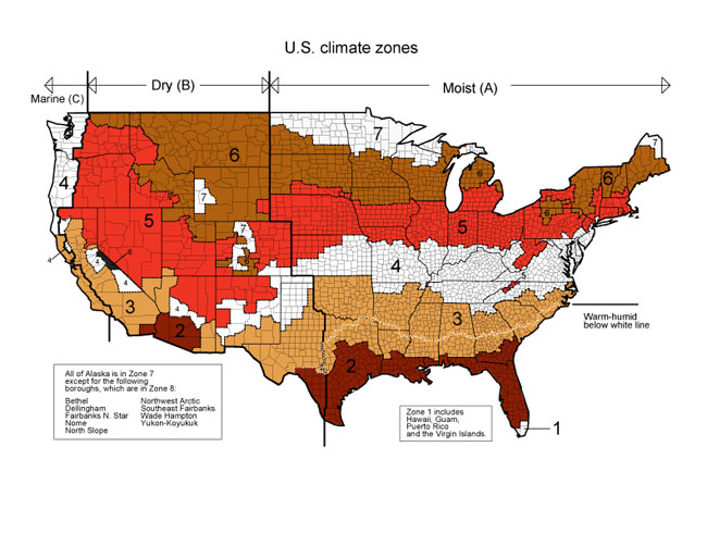
Figure 1: U.S. climate zones have varying minimum insulation requirements for residential buildings.
The minimum insulation requirements are an R-value of 30 for Climate Zones 1, 2 and 3; R-value of 38 for Climate Zones 4 and 5; and R-value of 49 for Climate Zones 6, 7 and 8.
There is an exception for buildings without attics, such as buildings with cathedral ceilings. In Climate Zones 4 through 8, if a roof and ceiling assembly's design does not allow sufficient space for required amounts of insulation, an R-value of 30 can be used. However, this reduction is limited to 500 square feet or 20 percent of the total insulated ceiling area. So, for example, if a cathedral ceiling spans the entire length of a building, the reduced R-value cannot be used.
The most common location for insulation is the cavity space, which is the space between the rafters or trusses. Typically, cavity insulation consists of fiberglass blankets or cellulose insulation. Relatively speaking, fiberglass insulation is the most commonly used insulation because it is inexpensive, readily available and familiar to contractors.
However, in many cases, fiberglass insulation isn't installed properly; it often is compressed to fit in a space or compacted around conduit, pipes or other obstructions, which reduces the R-value. Instead, the blankets should be cut to fit snugly so no air can pass through.
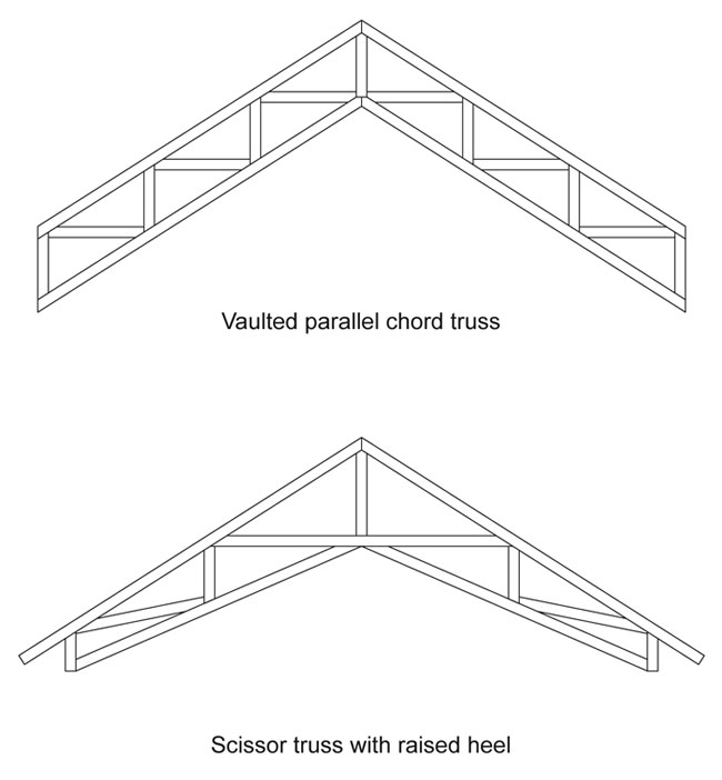
Figure 2: For buildings incorporating trusses, vaulted parallel chord trusses or scissor trusses with raised heels allow for greater insulation depths.
Cellulose insulation, which is blown into a cavity, tends to be more expensive and typically requires a professional installer. One advantage is this dense insulation material settles around pipes, conduits and obstructions with no gaps and inhibits air movement. And if sustainable materials are desired, cellulose insulation contains a high percentage of recycled material content.
Energy codes, high-performance green codes and programs such as LEED® are requiring R-values exceeding those that have been required historically. In many cases, conventional framing will not accommodate these increased insulation levels; designers and contractors should consider deeper rafters. For buildings incorporating trusses, vaulted parallel chord trusses or scissor trusses with raised heels (or energy heels) allow for greater insulation depths (see Figure 2).
Two insulation layers
For various reasons, insulation ideally should be placed as two layers.
For example, the required insulation amounts may not fit in the cavity space, so adding a second layer may be necessary. Another advantage is less thermal loss because there would be two layers for air to bypass. Also, if a compact roof assembly has an interior insulation layer—just inboard of the ceiling material—it can be rigid board material. Rigid board insulation can be taped or have sealed joints, which help prevent the passage of warm air.
Using furring strips to create an additional space allows room for electrical conduit and/or boxes and facilitates gypsum board attachment.
Insulation baffles
Regardless of the type of cavity insulation material used, insulation baffles should be used to maintain an unobstructed airway path and prevent air from passing through insulation. Pre-manufactured baffles, typically constructed from plastic, are available. If baffles are field-fabricated or custom-made, keep in mind they are exposed to a moist environment, and materials such as gypsum board may not be suitable.
Vapor retarder
Another consideration when reducing the passage of warm air is a vapor retarder, which should be placed on the warm (interior) side of roof insulation. The vapor retarder should be sealed off at wall terminations or tied into a wall's vapor retarder. Common vapor retarder materials include plastic sheets or films made from PVC or polyethylene.
Penetrations
Holes in the vapor retarder created by penetrations such as chimneys, plumbing chases, pipes, electrical conduit and recessed light fixtures should be sealed to prevent air passage. Reducing the amount of penetrations in the ceiling to prevent breaches in vapor retarders also is an important consideration.
Skylights warrant special discussion because they block airflow through airflow cavities. To permit some airflow around a skylight, holes may be drilled through the rafters just below the skylight. It often is debated whether the holes effectively will provide cross ventilation. In any event, if the decision is made to drill holes, the size and location of holes in the framing should be analyzed to ensure structural integrity.
Properly sized airway cavities
Much of the research regarding cathedral ceiling ventilation's role in reducing ice-dam formation has been performed by the U.S. Army Corps of Engineers at its Cold Regions Research and Engineering Laboratory (CRREL). The research, which was based on an interior temperature of 70 F, demonstrated that attic ventilation systems should be sized to keep a roof deck's underside below freezing when it is 22 F outside. The following factors were considered when sizing airway cavities: roof slope, roof system R-value and airway lengths (eave-to-ridge distance). See Figure 3 for the applicable charts for a cathedral ceiling that has a roof system with a 7:12 (30-degree) slope.
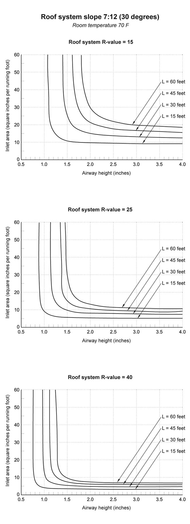
Figure 3: Airway heights and inlet areas for cathedral ceilings with a 7:12 (30-degree) slope
Consider the first graph in Figure 3. The cathedral ceiling will be insulated with an R-value of 15, and the eave-to-ridge distance is 30 feet. If the airway height is designed to be 1 3/4 inches high, what size should the inlet and outlet vents be? This graph is recreated in Figure 4 for purposes of this example.
In Figure 4, locate the airway height of 1 3/4 inches along the horizontal axis (X axis). Draw a vertical line from the airway height until it intersects the curve for L=30 feet. From that point, draw a horizontal line to the left until it intersects the vertical axis (Y axis) on the graph. The net free inlet area required is about 18 square inches per running foot, or 1 1/2 inches wide plus the additional area needed to account for the screening in a continuous soffit vent.
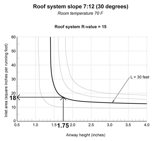
Figure 4: A demonstration of how to calculate the net free inlet area required
CRREL's research results also revealed that in many instances an airway height of 1 to 1 1/2 inches may not be adequate—especially 1 inch. A 1-inch height is a popular depth for some designers and builders; perhaps because one is a nice, round number or some vented nail-base insulation products have that depth. A 1 1/2-inch depth commonly is found because 2x4 lumber is installed as furring strips to create airway cavities.
The research indicates airway heights less than 1 1/2 inches may not be sufficient for some roof assemblies, such as those with shallow roof slopes—for example, 3:12 (14 degrees)—or with R-values less than 25 and/or eave-to-ridge lengths greater than 15 feet.
I encourage you to refer to The NRCA Roofing Manual: Architectural Metal Flashing, Condensation Control and Reroofing—2010 for more information regarding the CRREL research and guidelines addressing how to size airway cavities.
Intake and exhaust vents
Vents are an obvious but surprisingly forgotten issue. A compact roof assembly will not be ventilated properly without intake and exhaust vents. It is important to have vents at the eave/soffit area, at or near the ridge, and on all sides of the roof.
For information about intake and exhaust vents, refer to The NRCA Roofing Manual: Architectural Metal Flashing, Condensation Control and Reroofing—2010.
Protection membrane
A water and ice-dam protection membrane will help minimize the damaging effects of water leakage resulting from melting snow and ice dams. It is important to note a water and ice-dam protection membrane will not prevent ice dams from forming; it only will provide additional protection from moisture intrusion.
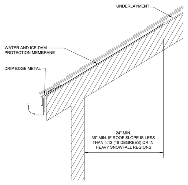
Figure 5: Installation of water and ice-dam protection membrane
A water and ice-dam protection membrane should be applied starting at a roof system's eaves and extend upslope a minimum of 24 inches from the inside of a building's exterior wall line. For slopes less than 4:12 (18 degrees) and in heavy snowfall regions, NRCA recommends the minimum distance be increased to 36 inches (see Figure 5).
To help readers visualize some suggestions I've discussed, Figure 6 is a schematic drawing of a ventilated cathedral ceiling.
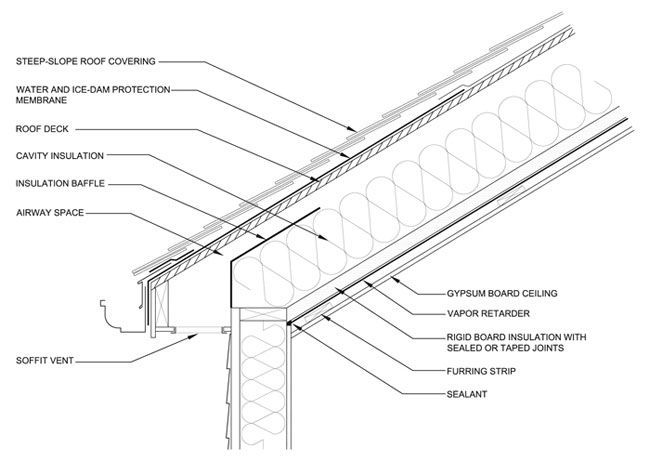
Figure 6: A schematic drawing of a ventilated cathedral ceiling
Existing construction
As previously mentioned, the best time to address cathedral ceiling issues is during the design phase. But the majority of calls NRCA's technical services department receives are about how to address cathedral ceiling issues in existing buildings. There is good news and bad news: The good news is there are some steps that can be taken to address such issues; the bad news is such steps probably are going to be expensive and disruptive.
Following are some considerations regarding what to do with an existing cathedral ceiling:
- Install a water and ice-dam protection membrane. As previously mentioned, this will help minimize the damaging effects of water leakage resulting from melting snow and ice dams. To properly install a water and ice-dam protection membrane, steep-slope roof covering materials must be removed and replaced. There are two options—a complete tear-off and replacement or a partial removal and replacement of roof covering materials. A partial removal and replacement presents another set of problems, such as matching color and style and potentially damaging the roof covering materials that remain in place. Additionally, a contractor may not warranty the work because the entire roof was not replaced; if there is a leak, it would be difficult to determine whether the leak's source is located in the existing roof system or replaced roof system.
- Eliminate gutters. At gutters, melted water collects, freezes and tends to back up under steep-slope roof coverings. Eliminating gutters at roof edges is a practical consideration to minimize ice dams. However, one of the downsides to this approach is uncontrolled water drainage.
- Add an airway cavity. The most elaborate solution is to add an airway cavity. This idea entails removing the existing steep-slope roof covering and installing furring strips, a nailable deck, underlayment and new roof covering materials. NRCA recommends a structural analysis be performed by a licensed structural engineer to determine whether the existing building can support the cavity's additional weight. Refer to The NRCA Roofing Manual: Architectural Metal Flashing, Condensation Control and Reroofing—2010 for additional information about the CRREL research and guidelines regarding how to size airway cavities.
In closing
It is important to note the ideas I present may not completely prevent the formation of ice dams and icicles, but they may help minimize their effects. And for an existing building, ice dam problems may not be solved with just one solution or limited to the roof assembly. The entire building may need to be considered and analyzed.
It may be in your best interest to seek help from a design professional who is familiar with cathedral ceiling design in heating climate zones.
Joan P. Crowe, AIA, is an NRCA director of technical services.
